original documentation:
https://learn.adafruit.com/mini-thermal-receipt-printer/overview
Power
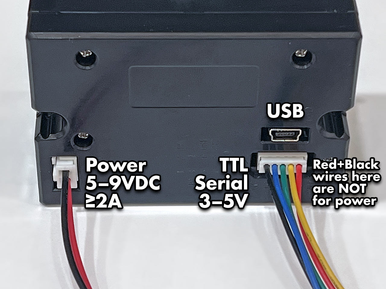
The Tiny printer has three sockets: a 2-pin connector for power, 5-pin for TTL serial communication, and a USB port. DO NOT attempt powering from the red and black wires of the serial cable. This cable is not following common electronics color conventions and connecting power here may damage the printer! Use ONLY the 2-pin connector for power.
Print Test Page
Most of these thermal printers have a test feature providing basic diagnostics. You’ll then know that power is good, paper is correctly loaded, and have some configuration details of the particular unit.
On most Mini and Tiny printers: hold down the button on the top of the printer while connecting power to print a test page. In normal use, tapping this button feeds the paper by one line.
For Product #2751: “Tiny”
The Tiny printer data cable has five wires:
Red = GROUND (yes, red, and yes this totally is the opposite of common electronics conventions)- Green = data IN to the printer (RX)
- Blue = data OUT of the printer (TX)
- Yellow (DTR) and black can be left unconnected
*The above description is not true to my Tiny Thermal Printer, my black wire is ground. It is labelled at the bottom of the printer.
This is in addition to the separate power cable, described on the prior page.
To Arduino
For a board like the Arduino Uno, the other end of the jumper wires can insert into the board edge sockets. For smaller devices on a breadboard, insert into the corresponding contact strip.
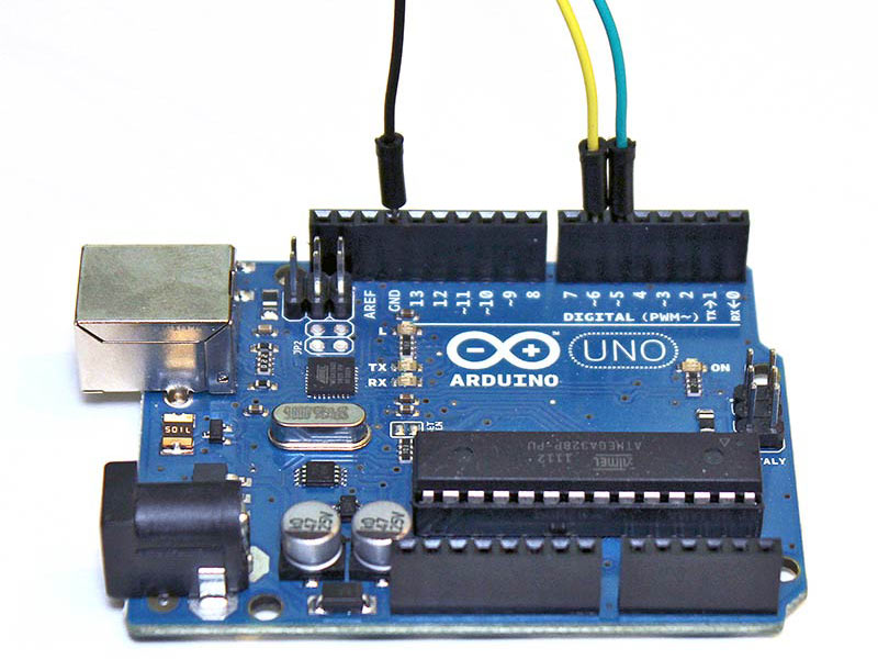
Ground from the printer always connects to GND on the microcontroller board. For the data wires (TX and RX), which pins to connect to can vary by hardware and software, explained further on subsequent pages. Some situations may require specific pins, but you can usually use any two pins. Here’s the printer’s TX line connected to digital pin 5, and RX to digital pin 6:
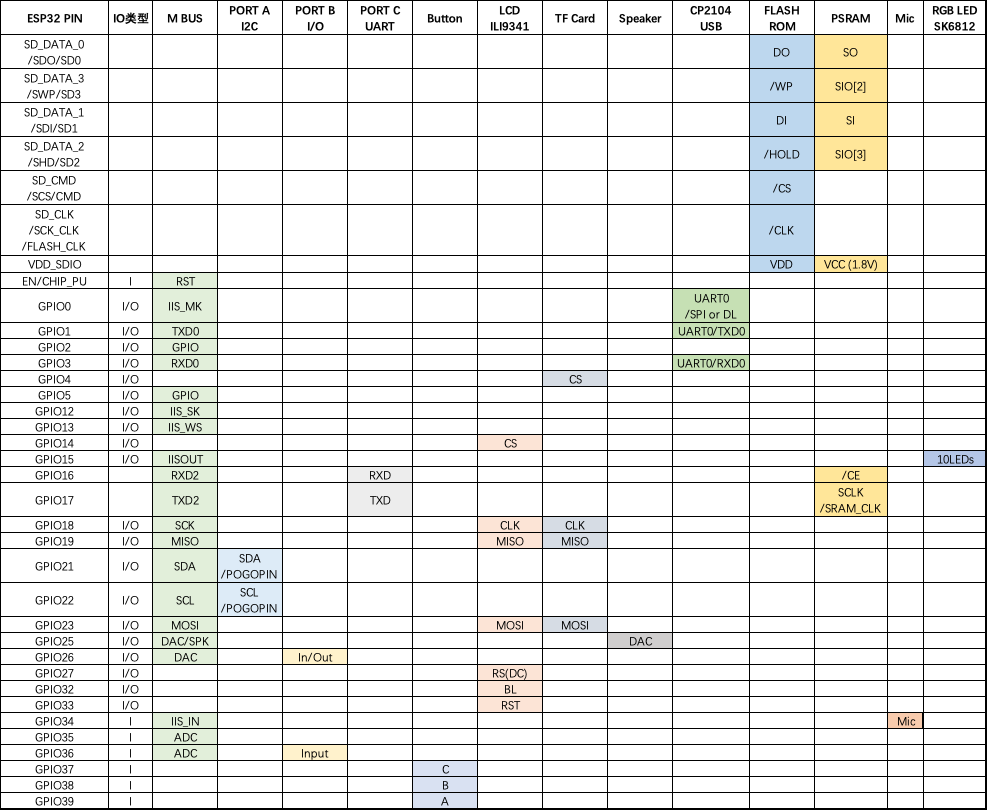
M5Stack Fire
GPIO 36 is INPUT ONLY, so rx has to be 36
Arduino Code
Connections are explained on the prior page. For the Arduino example code, we’ll connect the printer’s data out (TX) wire to digital pin 5, and data in (RX) to digital pin 6. Ground can go to any Arduino GND pin. Pins are configurable, but this is what the example uses, so let’s stick with that for now.
On the Arduino side, pin 5 receives (RX) and 6 transmits (TX)…opposite of the printer’s pin functions…called a crossover configuration, something you’ll hear a lot in serial communication and networking.
Install Library
We made an Arduino library to assist working with these printers.
Go to the Arduino Library Manager under Sketch→Include…Library→Manage…Libraries…
Search for and install the Adafruit Thermal Printer library
You should now be able to access the sample code by navigating through menus in this order: File→Sketchbook→Libraries→Adafruit_Thermal→A_printertest
If your printer test page shows ‘BAUDRATE: 9600’, you’ll need to make a small change to the library source code. Using a text editor (Notepad, etc.) open the file Adafruit_Thermal.cpp and change this line:
#define BAUDRATE 19200
Some printers arrive from the factory set for 19200 baud, but a few may be set to 9600. This will not negatively impact the performance of your unit! The speed of the paper through the printer is already much less than this and you will not see any difference…it’s strictly a data protocol issue of getting the microcontroller and printer communicating.
M5Stack Fire
Two places in the A_printertest sketch have to be modified to work with M5Stack Fire:
- Use Hardware serial. Make sure to pass the address (&Serial2) to the printer and initiate it properly in setup().
- Adafruit_Thermal’s setFont is conflict with the M5 one. Go into Adafruit_Thermal.h and Adafruit_Thermal.cpp and change the function name to something else. I changed setFont to setTPFont.
OK upload the sketch (with baudrate change if necessary) to the Arduino. You should see the printer print out the example receipt which includes all the capabilities of the library.
The thermal printer has a few handy things it can do, most of which are in the A_printertest sketch. These are shown in the image above. In order, starting from the top:
- Inverted text: this is invoked by calling inverseOn() — you will get text that’s white-on-black instead of black-on-white. inverseOff() turns this off.
- Double height: this makes text thats extra tall, call doubleHeightOn() — likewise, turn off with doubleHeightOff()
- Left/Center/Right justified: this aligns text to the left or right edge of the page, or centered. You can set the alignment by calling justify(‘R’) (for right-justified), justify(‘C’) (for centered) or justify(‘L’) (for left-justified). Left-justified is the default state.
- Bold text: makes it stand out a bit more, enable with boldOn() and turn off with boldOff()
- Underlined text: makes it stand out a bit more, enable with underlineOn() and turn off with underlineOff()
- Large/Medium/Small text: by default we use small, medium is twice as tall, large is twice as wide/tall. Set the size with setSize(‘L’), setSize(‘M’) or setSize(‘S’)
- Line spacing: you can change the space between lines of text by calling setLineHeight() where numpix is the number of pixels. The minimum is 24 (no extra space between lines), the default spacing is 32, and double-spaced text would be 64.
Look through the source of the A_printertest sketch to see these used in context.
Bitmap Printing
This printer can produce bitmaps, which can add a touch of class to a receipt with your logo or similar. Resolution: 8 dots/mm. 384 dots/line;
The first step is to get the image prepared. The printer can only do monochrome (1-bit) images, and the maximum width is 384 pixels. We suggest starting with a small bitmap (100 pixels or less on each side) and then experimenting to get the size and look you want.
A few steps are required to prepare an image for printing. For Windows users, there’s a nice graphical user interface for this. For Mac and Linux, different tools are used…not as visually slick, but they do the job well.
[Caution] These barcode printers shouldn’t be confused with a LaserJet – they’re not good at printing heavy/dense images with lots of black or they might stick and stall!
Windows
Use an image editing program to save your image as a 1-bit BMP — in Windows, the built-in Paint program will suffice.
Download, install and run LCD Assistant (https://en.radzio.dxp.pl/bitmap_converter/). This program is for Windows only but does a really fantastic job! Load the BMP file you previously generated (in Paint, etc.). The file must be in BMP format — the software won’t read PNG, GIF, etc. Then a couple of settings need to be adjusted…
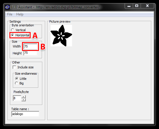
First, in the “Byte orientation” section of the settings, select “Horizontal” (item A in the image above).
Second (item B above), you may need to change the Width setting. Because this software (and the thermal printer) handle images in horizontal groups of eight pixels, if the image width is not a multiple of 8, it will be truncated (cropped) to the nearest smaller 8-pixel boundary. For example, with the 75 pixel wide image above, the output will be cropped to only 72 pixels wide, losing some data from the right edge. To avoid this, increase this number to the next multiple of 8 (that would be 80 for the example above), and the output will be padded with blank pixels to cover the gap. Remember the number you use here, you’ll need it later.
The image height does not need to be adjusted this way, only width.
Set the table name to something short but descriptive (e.g. “adalogo” above), then select Save Output from the File menu. Give the file a similarly brief but descriptive name, ending in “.h” (e.g. “adalogo.h”).
To get this file into your Arduino sketch, select “Add File…” from the Sketch menu. This will add a new tab to your code. Your original code is still there under the leftmost tab.
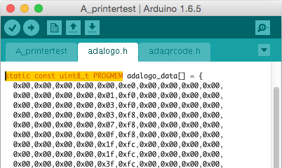
A couple of small changes are now needed in both tabs. First, at the top of the file containing the new table data, change “const unsigned char” to “static const uint8_t PROGMEM” as shown below:
Next, in the tab containing the main body of your code, add an “include” statement to reference the new file:
#include “adalogo.h”
Check the A_printertest example sketch if you’re not sure how to include the code properly.
You can now output the image by calling printBitmap(width, height, tablename), where width and height are the dimensions of the image in pixels (if you changed the image width to a multiple of 8 as previously described, use that number, not the original image size), and tablename is the name of the array in the new tab (e.g. “adalogo” above).
Having a graphical user interface is nice, but some of these extra steps can be confusing and error-prone. If you prefer, the technique below for Mac and Linux works in Windows as well.
Barcode Printing
Thermal printers are really good at printing barcodes! This printer supports 11 different codes – UPC A, UPC E, EAN13, EAN8, CODE39, I25, CODEBAR, CODE93, CODE128, CODE11 and MSI. It only supports linear (1-D) barcodes, and can’t generate 2-D barcodes like QR codes (although there is a hack you can do, see below!) Barcodes are generated “on the fly,” which is nice — you can customize the height and data included quite easily.
You can make a barcode by calling printBarcode(“barcodedata”, BARCODETYPE), where the first string is the data to encode (e.g. a UPC code) and BARCODETYPE can be UPC_A, UPC_E, EAN13, EAN8, CODE39, I25, CODEBAR, CODE93, CODE128, CODE11 or MSI.
Some barcodes are very restricted — you can only put in 12 numbers, no characters. Others are very flexible and take nearly any character input. Please check out the wikipedia list detailing kinds of barcodes to pick the right one for your application.
The available range of barcodes varies with the printer firmware revision. Check Adafruit_Thermal.h for a list of codes.
It’s also possible to print QR codes, if you’re willing to pre-generate them. This might be handy if you want to, let’s say, include a URL on the receipt and the URL doesn’t change. You can generate QR codes at many sites including this one. Use the smallest QR code size. The image will be in PNG format, so if you’re using the Windows LCD Assistant tool you’ll need to convert it to BMP first (Windows Paint works for this). Then you can convert and embed this in your Arduino sketch as previously described.
